(a) In a series LCR circuit connected across an ac source of variable frequency, obtain the expression for its impedance and draw a plot showing its variation with frequency of the ac source.
(b) What is the phase difference between the voltages across inductor and the capacitor at resonance in the LCR circuit ?
(c) When an inductor is connected to a 200 V dc voltage, a current of 1A flows through it. When the same inductor is connected to a 200 V, 50 Hz ac source, only 0.5 A current flows. Explain, why ? Also, calculate the self inductance of the inductor.
OR
(a) Draw the diagram of a device which is used to decrease high ac voltage into a low ac voltage and state its working principle. Write four sources of energy loss in this device.
(b) A small town with a demand of 1200 kW of electric power at 220 V is situated 20 km away from an electric plant generating power at 440 V. The resistance of the two-wire line carrying power is 0.5 Ω per km. The town gets the power from the line through a 4000-220 V step-down transformer at a sub-station in the town. Estimate the line power loss in the form of heat.
(a)
Let an inductor of inductance L, a resistance of resistance R and a capacitor of capacitance C be connected in series across an ac source of frequency f.
Let the current vary as
![]()
Where I is the current amplitude and ![]()
We know that the potential difference across the resistor is given by:
![]()
where VRm is the maximum potential across the capacitor and
![]()
We know that the potential difference across the capacitor is given by:
![]()
where VCm is the maximum potential across the capacitor
![]()
We know that the potential difference across the inductor is given by:
![]()
where VLm is the maximum potential across the capacitor and
![]()
Drawing the phasor diagram,
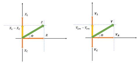
We can find the total potential difference across the three components by adding them. We do scalar addition for these potentials. This is same as adding the horizontal components of the phasors. Hence, we can do the vector addition of the phasors to get a new phasor V . The horizontal component of this phasor will give us the total potential difference across the three components.
![]()
Now, using the Pythagoras theorem, we have
![]()
Substituting ![]() ,
, ![]() and
and ![]() , we have
, we have
![]()
![]()
![]()
![]()
Impedance, Z, is defined as ![]()
Hence,
![]()
(b)
Note that the phase angle is the term inside the sine or the cosine.
The phase angle for the capacitor is
![]()
and the phase angle for the inductor is
![]()
Clearly,
![]()
Hence, the phase difference is π radians or 180° .
(c)
In a dc circuit, an inductor acts as a short circuit. Hence, it has negligible resistance. However, in an ac circuit, an inductor provides significant resistance known as inductive reactance. Thus, the current reduces.
Let us try to find the self-inductance.
Note that the inductor has some resistance. Hence, it can be though of as an ideal inductor in series with a resistor.
In the first circuit,
The resistance is given by:
![]()
(Note that the inductor acts as a short circuit)
OR
(a) Such a device is known as a step-down transformer.
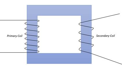
It is based on the principle of induction. If the current is changing through one coil, current is induced in a nearby coil.
The four sources of energy loss are flux leakage, resistance of the windings, eddy currents and hysteresis loss.
(b)
The town has power demand of 12000kW at 220V.
Resistance per unit length ![]()
Length of each wire ![]()
Total resistance, ![]()
The transformer steps down 4000V (![]() ) to 220V(
) to 220V( ![]() ).
).
If there is no power loss in the transformer, we can calculate the rms current in the lines by:
![]()
![]()
![]()
The power loss in the lines is
![]()
![]()
![]()
![]()