The capacitance between the adjacent plates shown in figure is 50 nF. A charge of 1.0 μC is placed on the middle plate.
a) What will be the charge on the outer surface of the upper plate?
b) Find the potential difference developed between the upper and the middle plates.

Given,
The charge given to the middle plate Q) is 1.0 μC
The capacitance between the plates, C is 50 nF=50× 10–3 μF
Formula used
For a capacitor with net charge, Q and capacitance, C, the Potential difference deceloped in between the plates, V is,
![]()
The charges on the inner plates of the capacitor with plates having charges Q1 and Q2 is,
![]()
Charges on the outer plates of the capacitor with plates having charges Q1 and Q2 is,
![]()
a)
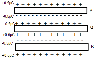
The charge given to the plate Q will be distributed equally on the either sides of plates as shown in figure. Hence the upper and lower sides of plate Q will be charged to +0.5 μC.
Here, we get two capacitors namingly as P-Q and Q-R.
In capacitor P-Q, the upper plate is neither connected to any battery nor given any charges. So the total charge on the plate is 0C. But when it is made into a capacitor plate, a charge is induced in it from the plate Q. The amount of the charge can be calculated from the eqn.2,
Which is,
![]()
Where Q1 is the charge on one plate Q= 1.0 μC
And Q2 is the charge on plate P = 0C
Hence by substituting in the above equation, we get,
![]()
Hence the inner surfaces get a charge of ±0.5μC on each plates. Since the plate Q is positively charged, Plate P will get -0.5μC charge.
But we know that the net charge on plate P is zero. Hence to nutralise the inner surface charge, the outer surface will get a charge of +0.5μC
b) From the above calculation, we found that the inner surfaces of the capacitor P-Q has a charge of ±0.5μC.
The potential difference between the plates can be found by the eqn.1, as
![]()
Hence the potential difference between the upper and middle plates of the arrangements is 10V.