i. Draw the pattern of magnetic field lines through and around a current-carrying solenoid. What does the magnetic field pattern inside the solenoid indicate?
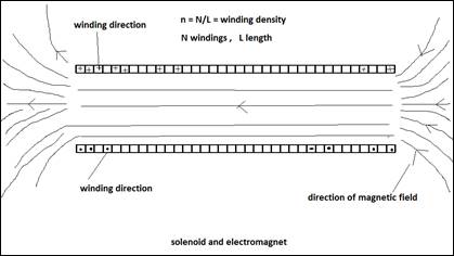
ii. How can this principle be utilised to make an electromagnet?
iii. State two ways by which strength of this electromagnet can be increased.
OR
Explain the underlying principle and working of an electric generator by drawing a labelled diagram. What is the function of brushes?
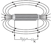
Magnetic field lines through a current carrying conductor loop are along its axis at its centre. As the solenoid of big length and small radius has a number of coils carrying the same current and have no gaps in between the windings, the magnetic lines add up.
The resulting magnetic field lines inside the solenoid become more or less uniform and aligned along the axis of the solenoid. At the edges they tend to diverge towards the opening. Outside the solenoid the effects of the neighbouring windings cancels out the magnetic field to zero.
ii. This principle is utilised to magnetise a piece of magnetic material like soft iron when placed inside the coil.
Can be used as an electromagnet-
Thus the cylindrical area inside a solenoid is an electromagnet by itself. We can also wrap a solenoid around a ferromagnetic material like iron, say, over half or full length of the bar. The bar can be bent in a shape of a "U"or a "horse shoe" or a "circle". Then the air gap between the two ends can be used as a magnetic field.
The empty solenoid can be bent in a shape of a horse shoe also.
iii. The strength of the electromagnet above is increased by adding more number of windings to the solenoid, increasing the number of windings per unit length, increasing the current, decreasing the diameter of solenoid.
It can be increased also by introducing a ferro-magnet of high paramagnetic property inside the solenoid.
It can be increased by adding another solenoid of larger diameter around the solenoid.
The strength of an electromagnet can be increased by immersing the solenoid and surroundings inside a paramagnetic fluid of high permeability.
B = μ₀ μ n i , n = windings/unit length, i = current
OR
An electric generator converts mechanical energy into electrical energy. Alternating current generators or AC generators produce alternating current. Principle: It works on the principle of electromagnetic induction. Whenever the magnetic flux through a coil changes, induced current is produced.
Construction: Alternating current generator consists of a rectangular coil ABCD called armature. The armature coil consists of large number of turns of insulated copper wire wound over a soft iron core. The coil is kept between the poles of a strong magnet. In the figure shown R1 and R2 are two slip rings connected to the two ends of the coil and convey the current produced to outside circuit. B1 and B2 are two carbon brushes remain in sliding contact with slip rings.
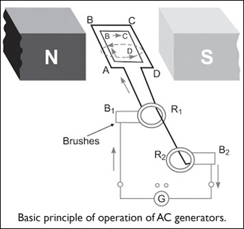
Working: The coil of the generator is rotated with the help of an axel. When coil rotates, it cuts the magnetic lines of force (magnetic field) near the north (N) and south (S) poles of the magnet. By electromagnetic induction, a current is induced in the coil. The direction of this current is given by Fleming’s right hand rule. As this coil turns clockwise, arm AB moves up and arm CD goes down. The direction of current is from A to B in AB and C to D in CD. The induced current is taken out through slip rings and carbon brushes. After half this rotation, AB and CD interchange their position. Now CD moves upward and AB downward. The direction of induced current is from D to C in CD and B to A in AB, during this half rotation. The slip rings R1 and R2 also rotate along with the coil ABCD. Thus, their polarities keep changing after every half rotation. Thus, the current changes its direction twice in one complete revolution of the coil. Such a current which changes its polarity after fixed intervals is called alternating current.
Function of Brushes: The brushes B1 and B2 remain fixed in their positions and maintain sliding contacts with the rotatable slip rings R1 and R2 respectively. It is through these brushes that the current induced in the armature coil is fed to the external circuit by means of line wires.