Figure shows a typical circuit for low-pass filter. An AC input Vi = 10 mV is applied at the left end and the output V0 is received at the right end. Find the output voltages for v = 10 kHz, 100 k Hz, 1.0 MHz and 10.0 MHz Note that as the frequency is increased the output decreases and hence the name low-pass filter.

Given: Voltage V1=10×10-3V,
Resistance (R) =1×10³ ohm,
Capacitance (C) =10×10-9 F
Angular velocity ![]() will be
will be
![]()
{a} At frequency (f) =10kHz
Reactance, ![]()
![]()
![]()
![]()
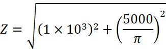
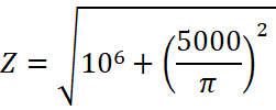
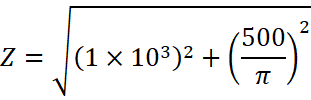
Impedance, ![]()
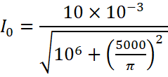
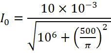
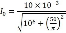
Then, Current (I0) will be
![]()
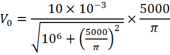
Thus, Output voltage (V0) will be
![]()
![]()
{b} At frequency (f) =100kHz
Reactance, ![]()
![]()
![]()
![]()
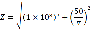
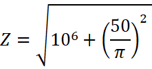
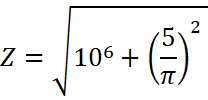
Impedance, ![]()

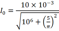
Then, Current (I0) will be
![]()
Thus, Output voltage (V0) will be
![]()

![]()
{c} At frequency (f) =1 MHz
Reactance, ![]()
![]()
![]()
![]()
Impedance, ![]()
Then, Current (I0) will be
![]()
Thus, Output voltage (V0) will be
![]()

![]()
{a} At frequency (f) =10 MHz
Reactance, ![]()
![]()
![]()
![]()
Impedance, ![]()

Then, Current (I0) will be
![]()
Thus, Output voltage (V0) will be
![]()

![]()
Couldn't generate an explanation.
Generated by AI. May contain inaccuracies — always verify with your textbook.