Skip to content
Philoid
Browse Saved
Back to chapter
Physics
14. Semiconductor Electronics
Home · Class 12 · Physics · Physics - Exemplar · 14. Semiconductor Electronics
Prev
Next
Q32 of 40 Page 93

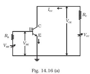
In the circuit shown in Fig.14.14, when the input voltage of the base resistance is 10V, Vbe is zero and Vce is also zero. Find the values of Ib, Ic and β.


The circuit diagram:


Applying KVL in the loop1,


Applying KVL in loop2,


We can find β from,


More from this chapter

All 40 →
30

A Zener of power rating 1 W is to be used as a voltage regulator. If zener has a breakdown of 5V and it has to regulate voltage which fluctuated between 3V and 7V, what should be the value of Rs for safe operation (Fig.14.12)?


31

If each diode in Fig. 14.13 has a forward bias resistance of 25 �Ω and infinite resistance in reverse bias, what will be the values of the current I1, I2, I3 and I4?


33

Draw the output signals C1 and C2 in the given combination of gates (Fig. 14.15).


34

Consider the circuit arrangement shown in Fig 14.16 (a) for studying input and output characteristics of n-p-n transistor in CE configuration.


Select the values of RB and RC for a transistor whose VBE = 0.7 V, so that the transistor is operating at point Q as shown in the characteristics shown in Fig. 14.16 (b).


Given that the input impedance of the transistor is very small and VCC = VBB = 16 V, also find the voltage gain and power gain of circuit making appropriate assumptions.


Questions · 40
14. Semiconductor Electronics
1 2 3 4 5 6 7 8 9 10 11 12 13 14 15 16 17 18 19 20 21 22 23 24 25 26 27 28 29 30 31 32 33 34 35 36 37 38 39 40
Back to chapter
ADVERTISEMENT
About Contact Privacy Terms
Philoid · 2026
  • Home
  • Search
  • Browse
  • Quiz
  • Saved