a) Draw the circuit diagram to determine the characteristics of a p- n-p transistor in common emitter configuration.
b) Explain, using I-V characteristics, how the collector current changes with the base current. How can (i) output resistance and (ii) current amplification factor be determined from the I-V characteristics?
OR
a) Why are photodiodes preferably operated under reverse bias when the current in the forward bias is known to be more than that in reverse bias?
b) The two optoelectronic devices: - Photodiode and solar cell, have the same working principle but differ in terms of their process of operation. Explain the difference between the two devices in terms of (i) biasing, (ii) junction area and (iii) I-V characteristics.
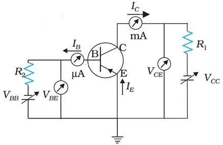
a) The circuit diagram to determine the characteristics of a p-n-p transistor is drawn below: -
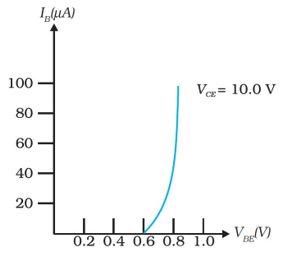
b) The output I-V characteristics obtained by observing the variation of IC (collector current) as VCE is varied keeping IB (base current) constant are shown below. If VBE is raised by a small amount, the hole current from the emitter region raises. Also, the electron current from the base region raises. This leads to increase in both IB and IC proportionately.

If IB increases, IC also increases. The plot of IC versus VCE for different fixed values of IB gives one output characteristic. So, there will be different output characteristics corresponding to different values of IB as shown,
i) Determination of Output Resistance: -
Output resistance (r0) is defined as the ratio of change in
collector-emitter voltage (ΔVCE) to the change in collector current (ΔIC) at a constant base current IB. So, it can be written as,
![]()
i) Determination of Current Amplification Factor: -
Current Amplification factor (β) is defined as the ratio of the change in collector current (IC) to the change in base current (IB) at a constant collector-emitter voltage (VCE) when the transistor is in active state. So, mathematically,
![]()
βAC also known as small signal current gain and its value is found generally very large. The ratio of IC and IB gives the DC β of the transistor. Hence,
![]()
Since IC increases with IB almost linearly and IC = 0 when IB = 0, the values of both βDC and βAC are approximately equal.
OR
a) Photodiodes are preferably operated under reverse bias when the current in the forward bias is known to be more than that in reverse bias because the photodiode converts incident light to electric current efficiently in reverse bias condition than in forward bias. This is due to the expansion of the depletion region of the diode. Photons after absorption generate electron hole pairs. The pairs generated in and around the region only contribute the electric current. In the forward bias condition, there is a strong electric field there to separate the two different charge carriers, so the pairs outside the region rapidly recombine and vanish also the width of depletion region decreases as there is an increase in the applied voltage so the effective number of photons contributing to the electric current decreases. But in reversed bias condition, the width of depletion region increases as there is an increase in the applied voltage, so, a large number of incident photons get converted into electric current, consequently the efficiency increases.
b) i) On the basis of biasing
A photodiode converts incident light to electric current in reverse bias condition whereas a solar cell is basically a diode which generates emf when solar radiation falls on the p-n junction. It works on the same principle (photovoltaic effect) as the photodiode, except that no external bias is applied.
ii) On the basis of junction area
photodiode is a simple p-n junction diode which is operated in reversed bias condition whereas a solar cell is a p-n junction diode in which the junction area is kept much larger for solar radiation to be incident and is not biased.
iii) On the basis of I-V characteristics
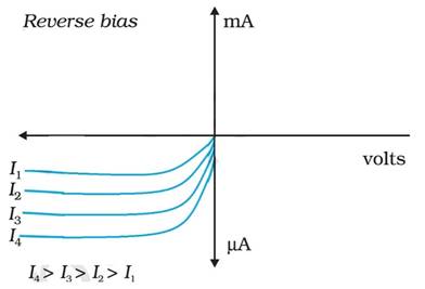
The I – V characteristics of a photodiode is drawn same as of a p-n junction diode in reverse bias condition as shown below
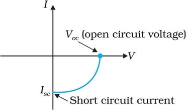
The I – V characteristics of solar cell is drawn in the fourth quadrant of the coordinate axes as shown in the diagram.
This is because a solar cell does not draw current but supplies the same to the load.
Couldn't generate an explanation.
Generated by AI. May contain inaccuracies — always verify with your textbook.
